NSX Advanced Firewall Add On for VMware Cloud on AWS (Part 3)

In my previous post, I talked about the FQDN filtering feature which is one of the new Add-Ons of the Advanced firewall.

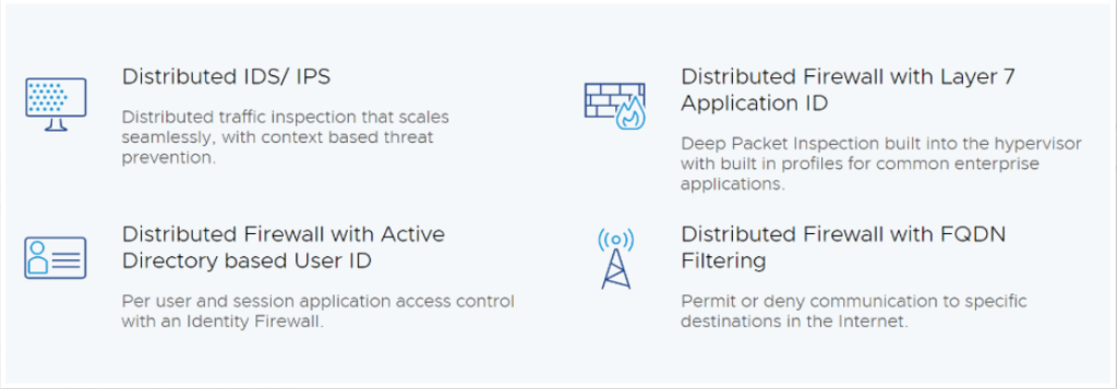
In this Part 3 of this multi part blog series, let’s focus on the latest feature, the Distributed IDS/IPS which is part of the newly announced NSX Advanced Firewall for VMware Cloud on AWS.

Introduction to Distributed IPS/IDS

With NSX Distributed IDS/ IPS, customers gain protection against attempts to exploit vulnerabilities in workloads running on VMware Cloud on AWS.

Distributed IDS/ IPS is an application-aware deep packet inspection engine that can examine and protect traffic inside the SDDC. Customers can detect and prevent lateral threat movement within the SDDC using the intrinsic security capabilities of Distributed IDS/IPS. 

Like DFW, Distributed IDS/IPS is built into the hypervisor and inspection can be performed for all traffic coming into or leaving the VM. Since the inspection is performed on all the hypervisor hosts in a distributed manner, there is no single inspection bottleneck that chokes the traffic flow.

Enabling Distributed IDS/IPS

First thing we will do is to activate and configure the Distributed IDS/IPS feature in VMC on AWS SDDC.

If you don’t have already activated the NSX Advanced Firewall add-on, please do so otherwise you will get this message:

Remember in my first Post of this series, I already have shown you how to activate the NSX Advanced Firewall Add On for VMware Cloud on AWS.

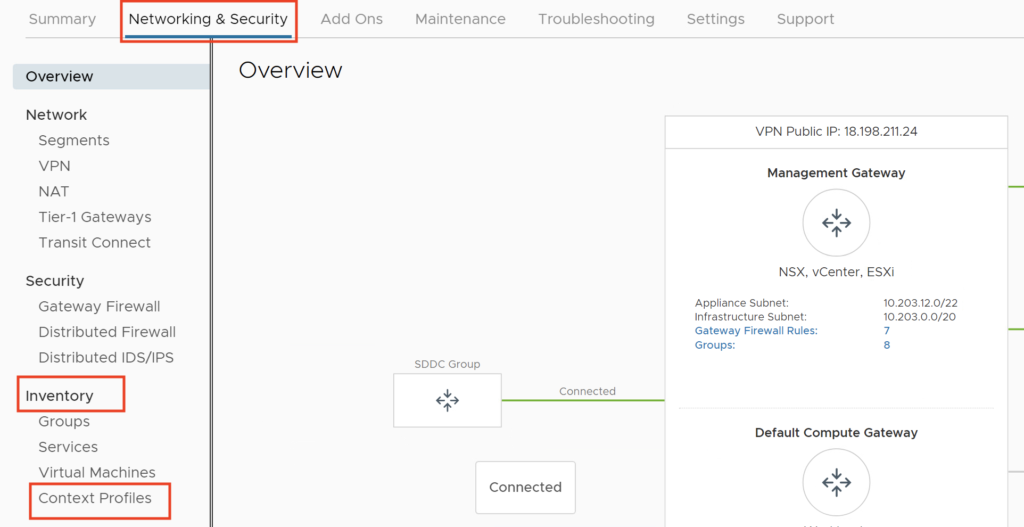
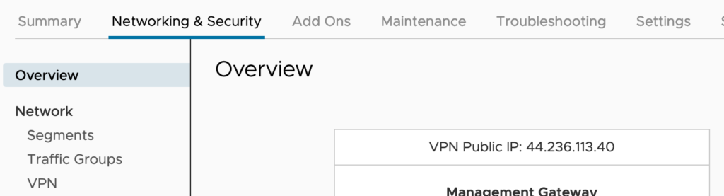
Once you have activated the add-on feature, in the browser, Click the Networking and Security tab. Click Distributed IDS/IPS, located in the Security Section.

The IDS/IPS is disabled by default so you have to enable it for the cluster. Here I have only one cluster.

Just move the slider to enable the feature and confirm that you want to enable the cluster and you are ready to test it!

Once it’s enabled you can choose to regularly update the Signatures by selecting the Auto Update new versions button.

NSX Distributed IDS/IPS utilizes the latest threat signature sets and anomaly detection algorithms to identify attempts at exploiting vulnerabilities in applications. It is integrated with the NSX Threat Intelligence Cloud Service to always remain up to date on the latest threats identified on the Internet.

You can check the other versions that have been presents in the environment by clicking the View and change versions link.

This is launching a new window with historical details. Here we can see that the first Default Signature was installed Jun 17th, 2021 and additional signatures has been pushed Oct 20th and Nov 12nd.

By clicking on the New signatures, I can dive deep into the details of each of them and access really good information on what signatures have been disabled, updated, …

We are gonna go ahead and be using the latest versions.

If you don’t have access to Internet from your NSX Manager, you also download the IDS/IPS signatures from the Network Threat Intelligence services page and be able to upload them manually.

Now it’s time to finish configuring the feature and launch some real test attacks by leveraging both Kali Linux and the infection Monkey tooling to simulate some attacks!

Configuring Distributed IDS/IPS profile & rule

Create a Profile for IDS/IPS

In this section, I will create a default profile to use with an IDS/IPS rule.

NB: We can configure up to 25 profiles.

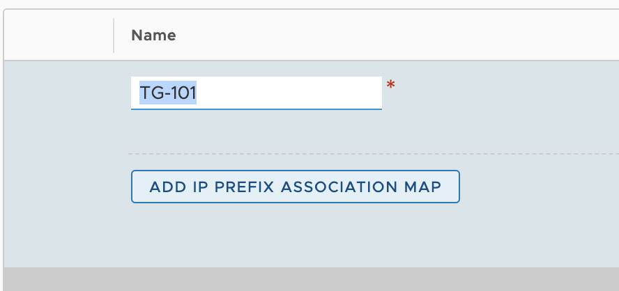
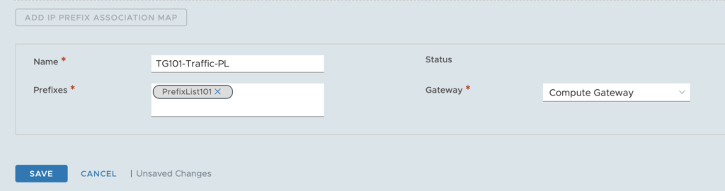
Under the Profiles tab under Distributed IDS/IPS within the Security section, I have clicked ADD PROFILE and create the ChrisIDSProfile profile:

I have accepted the default settings but you can customise the profile to meet your requirements. You can for instance only select the Intrusion attack with a level of severity to Critical or High and Critical only.

One thing you can do is to tweak it by selecting specific CVSS or Attack types.

I clicked save to finish creating the Profile.

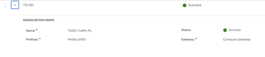
We can see that the profile has been successfully created.

After a few seconds it appears in green:

Create a Policy with rules for IDS/IPS

Now let’s create a Policy.

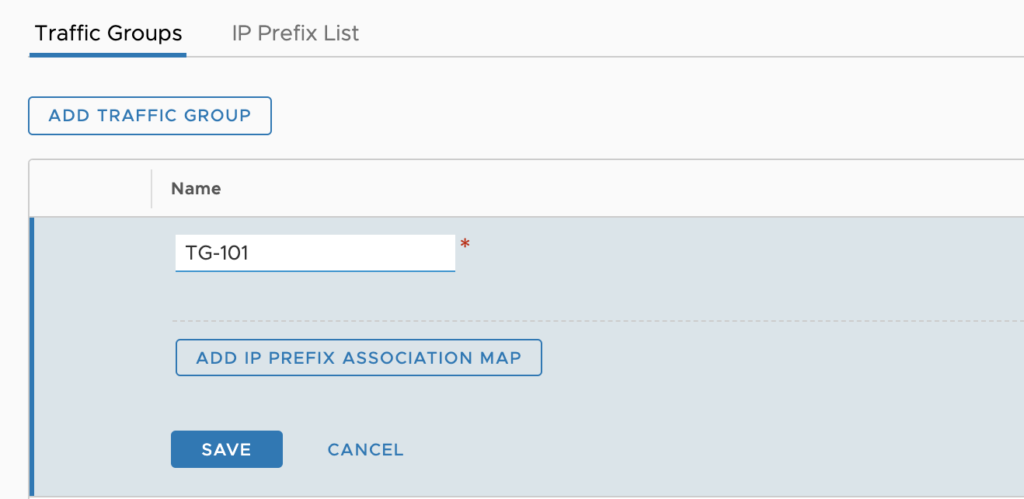
For that, I need to go to the Rules tab and add a specific IDS/IPS Policy called ChrisIDS-Policy.

I have selected the check box next to the name of the policy, then click Add Rule.

To finish the configuration I have to select the profile previously created.

I have also changed the source from Any to my SDDC subnets.

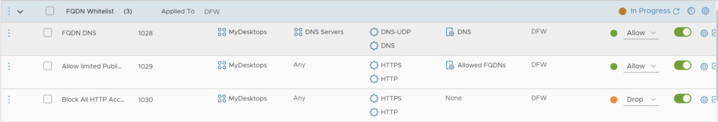
Please note that I leave the Sources and Services columns to Any and the Applied to field set to DFW.

I have also left the Mode to Detect Only. In Production it’s better to change this setting and switch to Detect & Prevent.

Now that I am done with the setup, I just need to click Publish.

Now it’s time to go for some tests of attacks and exploits.

Testing the IDS/IPS

In order to test the IDS/IPS feature, I have used my best security scanning tools to generate some attacks and try to exploit some vulnerabilities in one special server.

Basically I will launch the exploits on a OWASP Web Application server which is a test server with vulnerabilities that I have deployed in my SDDC. In a nutshell OWASP stands for The Open Web Application Security Project® and it is a nonprofit foundation that works to improve the security of software. It’s a very good way to test the level of security of your environment.

This OWASP server is going to be the target for all the vulnerability scanning coming from my two different tools.

Scanning tools

First one is the Kali Linux distribution in a Virtual Machine which have a multitude of security tools preinstalled in it. I love it!

The second one is the Infection Monkey virtual appliance from Guardicore which is a platform with a graphical interface that you can leverage to launch the exploits.

Infection Monkey is an open source breach and attack simulation (BAS) platform that allows organisations to discover security gaps and fix them. You can Simply infect a random machine with the Infection Monkey and automatically discover your security risks. Test for different scenarios – credential theft, compromised machines and other security flaws.

Deploying Kali Linux

It’s a simple process as you can install it from a ISO CD or download a virtual image directly from here.

I have choose to install it with the ISO CD as it gives more flexibility to tweak your VM settings.

Once the VM is deployed there is nothing more to do.

Deploying Monkey Island VM

First I have deployed the Monkey Island VM from the OVA downloaded from the Infection Monkey website. This is an Ubuntu Linux VM with a small footprint of only 2 vCPU and 2GB of RAM.

Once it’s been installed, I have just started the VM.

My VM is up and running very quickly and I can connect to it from the web console on port 5000:

Once I am logged in with the default username: monkeyuser and password, I can setup the system.

I start by clicking on Configure Monkey.

I need to click the Network tab, and Change the Target list IP address with the IP address of the OWASP VM running in the App segment (172.11.11.115).

Then I clicked on the Run Monkey on the left and Select From Island.

At that moment the tool launches the exploits automatically.

Launching the attacks and exploits

With Kali Linux tools

In my environment, the Kali Linux server address is 172.11.11.107.

And the OWASP Broken Web Application has the following address: 172.11.11.115.

In this first stage, I started to use Kali Linux with nmap to scan the OWASP Web server.

As you can see, there are 9 opened ports on the machine. The nmap command is able to output the name and version of the services that use the ports

Is this next step, I have leveraged the nikto command to scan for vulnerabilities on the server.

Multiple vulnerabilities have been displayed. Mainly affecting the Apache server and also the version of Python which is outdated

The result of the exploit is visible now on the CSP Console as you can see on the screen below. At the top, you can see there is representation of the attempt to compromise the server and they are spread over a time range with a slider that can be changed as needed.

The attacks have triggered a lot of Emerging Threats (ET Scan) alerts with Medium, High and Critical severity levels.

Medium alerts inform that the http protocol on the Web-Server is exploitable with vulnerabilities. The response here is just “Detect”. You can see the CVE number and CVSS Classification of the vulnerabilities on the right.

When I click on the VMs Affected, a list of the VM that have been affected by the vulnerabilities displays:

In addition, clicking the purple bar allow for displaying a detail window:

With Monkey Island tools

As I said before the scanner starts automatically after finishing the setup. Once it has finished its scanning operations, Monkey Island shows a map with all the results accessible through a web page.

It also displays a map of the devices that have been scanned by the tool.

On the right of the page, there is a tab called ATT&CK report that helps understand the exploits that have successfully been used or tried.

On the VMC on AWS Console, the results are displayed the same way as before with the Kali Linux tool:

The Alert displayed here is an apache Struts remote code execution attempt.

Conclusion

This new Advanced Firewall Add-on IDS/IPS feature is really interesting as today it’s the only way to prevent attacker from exploiting vulnerabilities from inside the SDDC.

That’s conclude the post, I hope this has given you a better understanding on how this feature is powerful.

NSX Advanced Firewall Add On for VMware Cloud on AWS (Part 2)

In my previous post, I have introduced you to the new Advanced Firewall Add-on in VMWare Cloud on AWS.

I also covered the Context Aware Firewall feature to filter connection based on the App id and not only the protocol number.

In this post, I am going to cover Distributed FW FQDN filtering to allow applications that communicate outside the SDDC gain layer 7 protection.

Introducing the FQDN Filtering feature

This feature can allow users to only access specific domains by whitelisting and/or blacklisting FQDNs. In many high-security environments, outgoing traffic is filtered using the Distributed firewall. When you want to access an external service, you usually create IP-based firewall rules. In some cases, you don’t know which IP addresses hide behind a domain. This is where domain filters come in handy.

Because NSX-T Data Center uses DNS Snooping to obtain a mapping between the IP address and the FQDN, you must set up a DNS rule first, and then the FQDN allowlist or denylist rule below it.

SpoofGuard should be enabled across the switch on all logical ports to protect against the risk of DNS spoofing attacks. A DNS spoofing attack is when a malicious VM can inject spoofed DNS responses to redirect traffic to malicious endpoints or bypass the firewall

You can define specific FQDNs that are allowed and apply them to DFW policies. Conversely, you can define specific FQDNs that are denied access to applications in the SDDC. The DFW maintains the context of VMs when they migrate. You can then increasingly rely on application profiling and FQDN filtering to reduce the attack surface of their applications to designated protocols and destinations.

Configuring DFW with FQDN filtering

In this section, I will show you how to setup a FQDN Context Profile, and a Firewall policy to limit access to specific URLs from VMs.

Creating a FQDN Context Profile.

First thing first ! Let’s create the context Profile.

Under Networking and Security, in the Inventory section, click Context Profile.

Click FQDNs Tab

Click ACTIONS –> Add FQDN

Enter the Domain: *.yahoo.com, and then Click SAVE.

Create a second FQDN with *.google.com.

Click the Context Profile Tab, and Click ADD CONTEXT PROFILE

Give it a Name: Allowed FQDNs, Click Set

Click ADD ATTRIBUTE –> Domain(FQDN) Name

Select the following domains: *.yahoo.com, *.office.com, *.google.com and Click ADD.

Click APPLY, Click SAVE. We now have a Context Profile setup.

Creating a Firewall rule and a Policy

I have created a Group called MyDesktops which includes a segment with my Windows VMs.

Now I am going to setup a Firewall Policy including this Context Profile. I will limit my VM in the MyDesktops group to access to the Allowed FQDNs. Also I limit access from this Group of VMs to specific DNS servers (8.8.8.8, 8.8.4.4).

I also add a Drop rule at the end to limit access to only the FQDNs that were whitelisted.

Now I am allowed to access google.com and Yahoo.com but I can’t connect anymore to the vmware.com site.

This concludes the post on FQDN Filtering. In my final post, I will cover the Distributed IDS/IPS feature.

NSX Advanced Firewall Add On for VMware Cloud on AWS (Part 1)

VMware Cloud on AWS already offers a robust sets of networking and security capabilities that enable customers to run production applications securely in the cloud.

The release of the M16 version is introducing new Advanced Firewall Features as an Add-on.

This includes the following new security capabilities:

  • L7 Distributed (Context Aware) Firewall with application ID – With L7 (Context-aware) firewall you can go beyond simple IP/ port level layer 4 security to complete stateful layer 7 controls and filtering.
  • L7 Distributed Firewall with FQDN Filtering – Applications that communicate outside the SDDC also gain layer 7 protection using Distributed Firewall FQDN filtering capability. Customers can define specific FQDNs you can define specific FQDNs that are denied access to applications in the SDDC. The DFW maintains the context of VMs when they migrate. Customers increasingly rely on application profiling and FQDN filtering to reduce the attack surface of their applications to designated protocols and destinations.
  • User Identity Firewall – You can create groups based on User ID and define DFW rules to control access to virtual desktops and applications in the SDDC. Per user/ user session access control limits the amount of time and exposure users have to desktops or applications. Integration with Active Directory / LDAP enables the DFW to continuously curate user access to applications. User ID based rules are enforced by the DFW at the source, delivering pervasive, intrinsic security throughout the SDDC.
  • Distributed IDS/IPS – With NSX Distributed IDS/ IPS, customers gain protection against attempts to exploit vulnerabilities in workloads on VMware Cloud on AWS. Distributed IDS/ IPS is an application-aware deep packet inspection engine that can examine and protect traffic inside the SDDC.

Let’s try them to see how it works!

Enabling the NSX Advanced Firewall Add-On

The NSX Advanced Firewall Add-on adds Layer-7 Firewall protection, Identity Firewalling, Distributed IDS/IPS and FQDN Filtering to the VMC on AWS SDDC. This Feature is an Add-on featured and priced in addition to the Standard VMC on AWS subscription.

Before any of these features can be used, you must first enable the add-on onto your SDDC. In the following section, I am going to walk you through the steps of enabling the NSX Advanced Firewall functionality onto your SDDC.

  1. On your SDDC tile, click View Details
  2. Click the Add-Ons tab
  3. In the NSX Advanced Firewall Tile, click Activate

Click Activate

Click OPEN NSX ADVANCED FIREWALL (This will take you to the Networking & Security Tab)

At this step, the NSX Advanced Firewall Addon has been enabled. To make use of the functionality it provides, you must configure them individually.

In the upcoming sections, we will configure and test each of these features.

Configuring L7 Distributed Context Aware Firewall

With L7 (Context-aware) firewall, it’s possible to go beyond simple IP/ port level layer 4 security to complete stateful layer 7 controls and filtering. This will avoid for instance someone from changing Port number to bypass a firewall rule.

Extremely powerful !

Deep packet inspection (DPI) built into the Distributed Firewall enables you to allow only the intended application / protocols to run, while denying all other traffic at the source. This enables you to isolate sensitive applications by creating virtual zones within the SDDC.

Distributed Firewall (DFW) layer 7 policies are enforced at the hypervisor (vNIC) level and can migrate with the VM when they move from host to host in the SDDC, ensuring there are no gaps in enforcement.

Let’s see how to configure and use the feature.

Configuring a standard L4 FW rule

In my example, I have two VMs (webserver01, webserver02) running in my SDDC which are part of a group called Web Tier.

Here are the IPs of the VMS:

They can communicate together over any protocol as this is the default settings in the Distributed Firewall as we can see here:

First let’s create a traditional L4 firewall rule to block SSH traffic between the two VMS.

Now if I want to ssh from webserver01 to webserver02 it’s blocked:

What if SSH was listening on another port, however? What if some nefarious person (knowing SSH on port 22 is being blocked) changed the port the server listens on and attempts to SSH to the server against this new port, what happens then? 

To do that I have edited the sshd_config on the webserver02 VM and changed the port to 2222:

I have then restarted the ssh service on the VM:

We can see the ssh server is now running on port 2222:

Let see what happens when we apply context awareness to the firewall rule.

now if I try to connect back but on port 2222, it works!

Unfortunately, the L4 DFW doesn’t block it. As mentioned earlier the firewall is looking for SSH on port 22, not port 2222, so I was able to bypass the firewall policy.

Configuring Context Aware Firewall rule

NSX Context-Aware Firewall  Rule (L7) enhances visibility at the application level and helps to override the problem of application permeability. Visibility at the application layer helps you to monitor the workloads better from a resource, compliance, and security point of view.

In order to switch to the Context Aware firewall, I just have to remove the SSH in the Service field from the DFW rule and need to add SSH in the Context Profile field:

The rule is now changed:

Let’s try to connect again to port 2222:

Now the attempt to connect to the modified port is block. That’s much better! This is because the DFW now assesses the packet at layer 7 and identifies the heuristics of the packet to be ssh and does not allow the traffic through.

With Context-Aware Firewalling you can enable enforcement of security protocol versions/ciphers reduce attacks by only allowing traffic matching APP Fingerprint, and enforce port-independent rules.

In the next post I will introduce you to the L7 Distributed Firewall with FQDN Filtering. Stay tune!

Introducing Multi-Edge SDDC on VMC on AWS

The latest M12 release of SDDC (version 1.12) came with a lot of interesting storage features including vSAN compression for i3en, TRIM/UNMap (I will cover it in a future post) as well as new networking features like SDDC Groups, VMWare Transit Connect, Time-based Scheduling of DFW rules and many more.

One that typically stands out for me is the Multi-Edge SDDC capabilities.

Multi-Edge SDDC (or Edge Scaleout)

By default, any SDDC is deployed with a single default Edge (actually this a pair of VMs) which size is based on the SDDC sizing (Medium size by default). This edge can be resized to Large when needed.

Each Edge has three logical connections to the outside world: Internet (IGW), Intranet (TGW or DX Private VIF), Provider (Connected VPC). These connections share the same host Elastic Network Adapter ENA and it’s limits.

In the latest M12 version of VMC on AWS, VMC is adding Multi-Edge capability to the SDDC. This gives the customer the ability to add additional capacity for North-South network trafic by simply adding additional Edges.

The goal of this feature is to allow multiple Edge appliances to be deployed, therefore removing some of the scale limitations by:

  • Using multiple host ENAs to spread network load for traffic in/out of the SDDC,
  • Using multiple Edge VMs to spread the CPU/Memory load.
The Edge Scale out feature consists in the creation of a pair of additional EDGEs where specific traffic type can be steered to

In order to be able to enable the feature, additional network interfaces (ENA) are going to be provisioned in the AWS network and additional compute capacity are created.

It’s important to mention that you do need additional hosts in the management clusters of the SDDC to be able to support it. So this feature is coming with an additional cost.

Multi-Edge SDDC – Use Cases

The deployment of additional Edges allow for an higher network bandwidth for the following use cases:

  • SDDC to SDDC connectivity
  • SDDC to natives VPCs
  • SDDC to on-premises via Direct Connect
  • SDDC to the Connected VPC

Keep in mind that for the first three, VMWare Transit Connect is mandatory to allow the increased network capacity by deploying those multiple Edges. As a reminder, Transit Connect is a high-bandwidth, low latency and resilient connectivity option for SDDC to SDDC communication in an SDDC groups. It also enables an high bandwidth connectivity to SDDCs from natives VPCs. If you need more information on it, my colleague Gilles Chekroun has an excellent blog post here.

Multiple Edges permits to steer certain traffic sets by leveraging Traffic Groups.

Traffic Groups

Traffic Groups is a new concept which is similar in a way to the source Based Routing. Source based routing allow to select which route (next hop) to follow based on the source IP addresses. This can be an individual IP or complete subnet.

With this new capability customer can now choose to steer certain traffic sets to a specific Edge.

At the time you will create a traffic group, an additional active edge (with a standby edge) is going to be deployed on a separate host. All Edge appliances are deployed with an anti-affinity rule to ensure only one Edge per host. So there need to be 2N+2 hosts in the cluster (where N=number of traffic groups).

Each additional Edge will then handles traffic for its associated network prefixes. All remaining traffic is going to be handled by the Default Edge.

Source base routing is configured with prefixes defined in prefix lists than can be setup directly in the VMC on AWS Console.

To ensure proper ingress routing from AWS VPC to the right Edge, the shadow VPC route tables are also updated with the prefixes.

Multi-Edge SDDC requirements

The following requirements must be met in order to leverage the feature:

  • SDDC M12 version is required
  • Transit Connect for SDDC to SDDC or VPC or SDDC to on-prem
  • SDDC resized to Large
  • Enough capacity in the management cluster

A Large SDDC means that management appliances and Edge are scaled out from Medium to Large. This is now a customer driven option that doesn’t involve technical Support anymore as it’s possible to upsize an SDDC directly from the Cloud Console.

Large SDDC means an higher number of vCPUs and memory for management components (vCenter, NSX Manager and Edges) and there is a minimal 1 hour downtime for the upscaling operations to finish, so it has to be planned during a Maintenance Window.

Enabling a Multi-Edge SDDC

This follow a three step process.

First of all, we must define a Traffic Group that is going to create the new Edges (in pair). Each Traffic group creates an additional active/standby edge. Remember also the “Traffic Group” Edges are always Large form-factor.

Immediately you will see that 2 additional edge Nodes are going to be deployed. The New Edges have a suffix name with tg in it.

Next step you have to define a prefix list with specific prefixes and associate a Prefix List. It will contain the source IP adresses of SDDC virtual machines that will use the newly deployed Edge.

After some minutes, you can confirm that the Traffic groups is ready:

NB: NSX-T configures source based Routing with the prefix you define in the prefix list on the CGW as well as the Edge routers to ensure symmetric routing within the SDDC.

You just need to click on Set to enter the prefix list. Enter the CIDR range, it could a /32 if you just want to use a single VM as a source IP.

NB: Up to 64 prefixes can be created in a Prefix List.

When you done entering the subnets in the prefix list, Click Apply and Save the Prefix List to create it.

Last step is to associate the Prefix List to the Traffic Group with Association Map. To do so click on Edit.

Basically we now need to tell what prefix list to use for the traffic group. Click on ADD IP PREFIX ASSOCIATION MAP:

Then we need to enter the Prefix List and give a name to the Association Map.

Going forward any traffic that matches that prefix list will be utilising the newly deployed Edge.

Monitoring a Multi-Edge SDDC

Edge nodes cannot be monitored on VMC Console but you can always visualise the Network Rate and consumption through the vCenter web console.

When we look at the vCenter list of Edges, the default Edge has no “-tg” in its name. So basically the NSX-Edge-0 is the default. As long as we add the new traffic group, the traffic is going to manage the additional traffic and liberate the load on this default Edge.

The NSX-Edge-0-tg-xxx is the new one and we can see an increase on this new Edge in the traffic consumption on it now because of the new traffic going to flow over it:

What happened also after the new scale edge is deployed, is that the prefix list is using the new Edge as its next-hop going forward. This is also propagated to the internal route tables from Default Edge as well as CGW route table.

All of these feature is exposed over the API Explorer, for the traffic Groups definition in the NSX AWS VMC integration API. Over the NSX VMC Policy API for the prefix list definition perspective.

In conclusion, remember that Multi Edge SDDC doesn’t increase Internet capacity nor VPN or NAT capacity. Also that there is a cost associated to it because of the additional hardware requirements.

Configure VPN from VMC to WatchGuardTM Firebox Cloud – Part 4 (Final)

In the previous posts of this series on Configuring a VPN connection from WatchGuard TM Firebox to VMC, I have showed you how to setup the Firebox and how to establish a VPN with a native VPC.

In this last post, I will attach the SDDC to the WatchGuard Firebox instance with a IPSEC route-based VPN leveraging BGP to allow for dynamic routes exchange.

With this configuration, any compute and management segments created inside the SDDC will be the advertised into the BGP session established with the Firebox in the transit VPC.

Firebox to SDDC IPSec VPN configuration

Phase 1 – VPN’s VPC configuration

First of all I need to collect the public IP address of my SDDC. This is possible by logging to the VMC Console and going to the Networking and Security tab, and Selecting the Overview window:

The IP of VPN is displayed as VPN Public IP. This Public IP is unique for any other VPN being established.

N.B.: You can also request additional public IP addresses to assign to workload VMs to allow access to these VMs from the internet. VMware Cloud on AWS provisions the IP address from AWS.

Next I’ll collect the BGP local ASN number of the SDDC. Just like IP addresses, ASNs (Autonomous System Numbers) have to be unique on the Internet and the SDDC utilises two numbers: one for the route-based VPN and one for Direct Connect

To do that I Click on Edit Local ASN option in the VPN window:

Clicking EDIT LOCAL ASN displays the Local ASN of the SDDC as shown here:

The local ASN of any brand new SDDC is by default at 65000. You can change it to a value in the range 64521 to 65535 (or 4200000000 to 4294967294).

N.B.: Keep in mind that the remote BGP ASN number need to be different.

Now it’s time to create a new Customer Gateway and map it to the SDDC settings.

Create a New Customer Gateway

For that I need to go back to the AWS console and Go to the VPC Dashboard and Select Customer Gateways under VIRTUAL PRIVATE NETWORK Menu on the left.

I Click Create Customer Gateway and choose Dynamic as a routing option, and add the public Elastic-IP address of the SDDC public IP.

I also need to specify the BGP ASN to the SDDC value (65000 by default). Note that it has to be different from the BGP ASN of the Firebox in the transit VPC.

Phase 2 – FireBox’s VPN Configuration

Now I have to setup the VPN configuration on the Firebox itself. For this, I connect back to the Fireware Web UI:

  1. Open a web browser and go to the public IP address for your instance of Firebox Cloud at: https://<eth0_public_IP>:8080
  2. Log in with the admin user account. Make sure to specify the passphrase you set in the Firebox Cloud Setup Wizard.

Select VPN, BOVPN Virtual Interfaces on the left and click the lock to open the settings window.

Enter a name for the interface (eg. BoSddc) and switch the Remote Endpoint Type to Cloud VPN or Third-Party Gateway.

In the Gateway Settings-> Credential Method, Enter a Use Pre-Shared Key (note the key as you will have to use it in the SDDC setup):

In the Gateway Settings–>Gateway Endpoint–>Click ADD.

Select Local Gateway–>Interface: Select Physical: External

Specify the gateway ID for tunnel authentication: Select By IP address: 34.210.196.xxx (this is the public Elastic-IP of the Watchguard Firebox)

Select Remote Gateway–>Specify the remote gateway IP address for a tunnel: a the Static IP Address has to be set to the Public IP address of the SDDC:

Next Step, Select Advanced tab and Click OK

Configure Phase 1 of IPSEC Proposal

Check ‘Start Phase1 tunnel when it is inactive‘ and Keep the ‘Add this tunnel to the BOVPN-Allow policies‘ checked.

The Phase 1 Settings should be as follow:
1. Version: IKEv1
2. Mode: Main
3. Uncheck NAT Traversal

N.B.: NAT Traversal is enabled by default but if your WatchGuard device is not behind a NAT/PAT device, please deselect NAT Traversal.

Dead Peer Detection:
a. Traffic idle timeout: 10
b. Max retries: 3

Transform Settings–>Click ADD:

1. Authentication: SHA1
2. Encryption: AES(128-bit)
3. SA Life: 8 hours
4. Key Group: Diffie-Hellman Group 2

Click OK.

Remove any pre-existing Phase 1 Transform Settings eg. SHA1-3DES.

Configure Phase 2 of IPSEC Proposal

Go to VPN–>Phase2 Proposals–>Click ADD

Name: AWS-ESP-AES128-SHA1
Description: AWS Phase 2 Proposal
Type: ESP
Authentication: SHA1
Encryption: AES(128-bit)
Force Key Expiration: Select ‘Time’ -> 1 hours

Click SAVE.

Go to VPN–>BOVPN Virtual Interfaces–>Select BoSddc–>Click EDIT

Phase 2 Settings–>Perfect Forward Secrecy:

Check ‘Enable Perfect Forward Secrecy’: Diffie-Hellman Group 2
IPSec Proposals–>Click on existing proposal–>Click REMOVE
Select ‘AWS-ESP-AES128-SHA1’ from the drop-down menu–>Click ADD

Click SAVE.

Configure BGP dynamic routing.

Go to VPN–>BOVPN Virtual Interfaces–>Select BoSddc–>Click EDIT

For the VPN Routes settings, I keep ‘Assign virtual interface IP addresses‘ option checked for the Interface option.

Then I setup the Local IP address to: 169.254.85.186 and Peer IP address or netmask to: 255.255.255.252

then Click SAVE.

Go to Network–>Dynamic Routing and Check ‘Enable Dynamic Routing’.

Click on ‘BGP’: Check ‘Enable’

I have to Add the below BGP dynamic routing configuration commands in the box:

router bgp 65001    N.B.: Use this command only once at the beginning of the BGP config as this the local ASN number that the Firebox will use for any VPNs.

NOw it’s time to add the configuration for the second BGP neighbor that we need to configure for the SDDC:

neighbor 169.254.85.185 remote-as 65000
neighbor 169.254.85.185 activate
neighbor 169.254.85.185 timers 10 30

Click SAVE.

Phase 3 – VMC on AWS SDDC’s VPN Configuration

VMC on AWS allows to create up to 4 IPSEC route-based VPN tunnels to be established between Firebox/VPC and your SDDC. To create the VPN on the SDDC side, you first have to Connect to the SDDC console.

Then you need to Go to the Networking & Security tab.

Select Network -> VPN and Click on the Route Based tab.

Click ADD VPN.

Next, you have to enter the following configuration settings:

  • First give a name to the IPSec VPN (eg. TOFirebox).

Select Local Public IP1 of the SDDC: this is the public IP address of the SDDC. As the Remote Public IP, Select the Elastic IP that was assigned to the public interface of the Watchguard Firebox FW. The Remote private IP is automatically entered.

For the BGP Local IP/Prefix Length, choose the following: 169.254.85.185/30.

The BGP Remote IP is the Local IP configured previously in the VPN Routes of the BOVPN Virtual interfaces: 169.254.85.186.

BGP Neighbor ASN has to be he remote ASN of the WatchGuard Firebox: 65001.

  • Tunnel Encryption: AES128
  • Digest Algorithm: SHA-1
  • PFS: Enabled
  • Diffie-Hellman: Group 2
  • IKE Encryption: AES128
  • IKE Digest:  SHA-1
  • IKE Type: V1

After a few seconds, we can see that the VPN is up!

Configure VPN from VMC to WatchGuardTM Firebox Cloud – Part 3

In this Part, I will show you how to configure an IPsec VPN from the “spoke” native VPC to the Firebox instance deployed in the transit VPC. This permits to leverage the Watchguard Firewall instance in the transit VPC as a filtering device from any trafic coming outside (SDDC, spoke VPC, on-prem).

Phase 1 – VPC’s VPN Configuration

In order to configure the VPN in the VPC, I need to do some preparation in the native VPC which consists in creating a Customer Gateway, a Virtual Private Gateway and attach them together.

To do so, let’s first Connect to the AWS console again!

Select IAM User and enter ID of your AWS account

Log in with the user account that have the administrative privileges on this account.

Create a Customer Gateway

NI have to go to the VPC Dashboard and Select Customer Gateways under VIRTUAL PRIVATE NETWORK Menu on the left.

I click Create Customer Gateway and choose Dynamic as a routing option, add the public Elastic-IP address of the FW. Specify the BGP ASN to a value different from the potential peer.

Create a Virtual Private Gateway

I’ll now create a brand new Virtual Private Gateway and attach it to the spoke VPC created earlier.

The VGW appears as detached:

I’ll select it and in the Actions drop-down menu, I select Attach to VPC option:

It now shows as attached:

Create a VPN Connection

Now I will create the VPN Connection by associating the VGW to the Customer Gateway that I have created:

Once the VPN connection available, I select Download Configuration. This will open the following window:

I select Watchguard, inc. as a Vendor and click Download button. A file containing all the configuration is created. I am going to use it to configure the Firebox now.

Phase 2 – FireBox’s VPN Configuration

First I need to Connect to Fireware Web UI by opening a web browser to the public IP address of the Firebox Cloud instance
https://<eth0_public_IP>:8080

I log in with the admin user account and I make sure to specify the passphrase I have set in the Firebox Cloud Setup Wizard.

Then I Select VPN, BOVPN Virtual Interfaces on the left and click the lock icon.

First I started by following the instruction in the VPN configuration file downloaded earlier.

So I enter the interface name and switch the Remote Endpoint Type to Cloud VPN or Third Party Gateway.

In the Gateway Settings-> Credential Method, I have entered the Use Pre-Shared Key stated in the file:

In the Gateway Settings–>Gateway Endpoint–>Click ADD:. Select Local Gateway–>Interface:

I need now to Specify the gateway ID for tunnel authentication. I select By IP address: here I enter the following 34.210.196.xxx (this is the public Elastic-IP of the firebox).

Now I have to Select Remote Gateway–>Specify the remote gateway IP address for a tunnel to Static IP and enter the public IP of my SDDC.

Select Advanced–>Click OK

I have checked ‘Start Phase1 tunnel when it is inactive‘ and kept the ‘Add this tunnel to the BOVPN-Allow policies‘ checked.

We need to select the following for Phase 1 Settings:

1. Version: IKEv2
2. Mode: Main
3. Uncheck NAT Traversal

NAT Traversal is enabled by default but if your WatchGuard device is not behind a NAT/PAT device, please deselect NAT Traversal.

For the Dead Peer Detection, choose the following values:

a. Traffic idle timeout: 10
b. Max retries: 3

Next we have to change the Transform Settings by clicking ADD et setup the following values:

1. Authentication: SHA1
2. Encryption: AES(128-bit)
3. SA Life: 8 hours
4. Key Group: Diffie-Hellman Group 2

Click OK and Remove any pre-existing Phase 1 Transform Settings (eg. SHA1-3DES).

Now we need to configure Phase 2 of IPSEC Proposal.

I need to Go to VPN–>Phase2 Proposals–>Click ADD:

  • Name: AWS-ESP-AES128-SHA1
  • Description: AWS Phase 2 Proposal
  • Type: ESP
  • Authentication: SHA1
  • Encryption: AES(128-bit)
  • Force Key Expiration: Select ‘Time’ -> 1 hours

Click SAVE.

  1. Go to VPN–>BOVPN Virtual Interfaces–>Select vpn-054bfd003f8ac9d2d-1–>Click EDIT

Phase 2 Settings–>Perfect Forward Secrecy:

Check ‘Enable Perfect Forward Secrecy’: Diffie-Hellman Group 2
IPSec Proposals–>Click on existing proposal–>Click REMOVE
Select ‘AWS-ESP-AES128-SHA1’ from the drop-down menu–>Click ADD

Click SAVE.

Phase 3 – Configure BGP Routing

It’s now time to configure BGP dynamic routing.

  1. Go to VPN–>BOVPN Virtual Interfaces–>Select vpn-054bfd003f8ac9d2d-1–>Click EDIT
  2. VPN Routes:

In the Interface window, keep ‘Assign virtual interface IP addresses‘ option checked:

Click SAVE.

Go to Network–>Dynamic Routing

Check ‘Enable Dynamic Routing’

Click on ‘BGP’ tab:

Check ‘Enable

Add the BGP dynamic routing configuration commands in the box as seen above.

We have to add the line: router bgp 65001  but only once at the beginning of the BGP config.

Click SAVE.

Phase 4 – Check tunnel is established

Go back to AWS Console to check VPN are established:

AWS allows the creation of a second tunnel to be established between the spoke VPC and the Firebox instance. To create the second VPN session, create a second tunnel by following the same instruction as above with the parameters described in the configuration file downloaded earlier.

That concludes the Part 3 of this post. In the next final Part, I will show you how to establish a VPN from SDDC to the Firebox instance in the transit VPC.

Configure VPN from VMC to WatchGuardTM Firebox Cloud – Part 2

Phase 2 – Deploy the WatchGuard Firebox instance

In Part 1 of this blog post, we have deployed a new transit VPC with two subnets and a route table configured accordingly.

Now it’s time to deploy a WatchGuard FW cloud EC2 instance in the transit VPC. This is possible from the EC2 dashboard:

  • After logging on the AWS Console with my personal AWS account, I have selected Services > EC2.
  • In the EC2 Dashboard, I can easily launch a new instance by Clicking on Launch instance (easy :=)),
  • I have selected AWS Marketplace and type ‘firebox’ in the search window and have decided to pick the Watchguard Firebox Cloud (Hourly) AMI.
  • You will get the pricing details and Click Continue
  • Select the smallest available instance with free tier t2.micro instance type and click Next: Configure Instance details
  • The configure Instance Details step opens.
  • From the Network drop-down list, select your transit VPC :
  • From the Subnet drop-down list, select the public subnet to use for eth0.
    The subnet you select appears in the Network Interfaces section for eth0.
  • To add a second interface, in the Network interfaces section, click Add Device.
    Eth1 is added to the list of network interfaces.
  • Click Next: Add Storage
  • Use the default storage size (5 GB). 
  • Click Next: Add Tags
  1. Click Next: Configure Security Group. By default, the instance uses a security group that functions as a basic firewall. This security group restricts following ports: HTTPS (TCP 8080), SSH, TCP 4118 (WatchGuard Firewalls may allow remote management using WSM (WatchGuard System Manager) over ports 4117, 4118 TCP).
  1. Click Review and Launch.
    The configured information for your instance appears.
  2. Click Launch.
    The key pair settings dialog box opens.

Phase 3 – Finish configuring the instance of the Firebox

In this phase we will finish configuring the EC2 instance of our Firebox.

Once the firewall is deployed, from the EC2 Dashboard, Click on the instance option, the new instance should appear as here:

Disable Source/Destination Checks

By default, each EC2 instance completes source/destination checks. For the networks on your VPC to successfully use your instance of Firebox Cloud for NAT, you must disable the source/destination check for the network interfaces assigned to the Firebox Cloud instance.

Disabling source/destination checks for the public interface is quite simple:

  • From the EC2 Management Console, select Instances > Instances.
  • Select the instance of Firebox Cloud.
  • Select Actions > Networking > Change Source/Dest. Check. The confirmation message includes the public interface for this instance.
  • Click Yes, Disable.
    The source and destination checks are disabled for the public & private interface.

Assign an Elastic IP Address to the External Interface

You must assign an Elastic IP (EIP) address to the eth0 interface for the instance of Firebox Cloud. You can use any available EIP address. To make sure you assign it to the correct interface, find and copy the eth0 interface ID of your instance of Firebox Cloud.

To find the eth0 interface ID for your instance of Firebox Cloud:

  1. From the EC2 Management Console, select Instances.
  2. Select the instance of Firebox Cloud.
    The instance details appear.
  3. Click the eth0 network interface.
    More information about the network interface appears.
  4. Copy the Interface ID value.

To associate the Elastic IP address with the eth0 interface:

  1. From the EC2 Management Console, select Network & Security > Elastic IPs.
  2. Select an available Elastic IP address.
  1. Select Actions > Associate Elastic IP Address.
    The Associate Elastic IP Address page opens.

If you have created 2 sub-interfaces, You can associate two different publics IPs to the interface:

Run the Firebox Cloud Setup Wizard

After you deploy the Firebox Cloud instance, you can connect to Fireware Web UI through the public IP address to run the Firebox Cloud Setup Wizard. You use the wizard to set the administrative passphrases for Firebox Cloud.

  1. Connect to Fireware Web UI for your Firebox Cloud with the public IP address:
    https://<eth0_public_IP>:8080
  2. Log in with the default Administrator account user name and passphrase:
    • User name — admin
    • Passphrase — The Firebox Cloud Instance ID

The Firebox Cloud Setup Wizard welcome page opens.

  • Click Next.
    The setup wizard starts.
  • Review and accept the End-User License Agreement. Click Next.
  1. Specify new passphrases for the built-in status and admin user accounts.
  2. Click Next.
    The configuration is saved to Firebox Cloud and the wizard is complete.

This is the end of Part 2, in Part 3 we are going to configure the IPSEC route based VPN between the Firebox instance and both a native VPC and a VMC on AWS SDDC.

Configure VPN from VMC to WatchGuardTM Firebox Cloud – Part 1

When I look back I realise I have been working at VMware for about 9 months and I have spent a tremendous amount of time dealing with a high number of requests, questions and issues with my customers.

One that particularly stands out is around integrating VMC on AWS with a Firewall hosted in a transit VPC for security purpose.

One of my customer recently was asking me if it was possible to create a VPN from VMC to a WatchguardTM Firebox Cloud Firewall. So I decided I would give it a try.

In this guide, I will first show you how to set up a route-based VPN from the WatchguardTM firewall to an AWS VGW in a native VPC.

In the last part, I will show how to configure an IPSEC route-based VPN from VMC on AWS to the same instance of WatchguardTM firewall hosted in a transit VPC.

Network Architecture diagram

Transit VPC with VPNs attachment to VMC and a native VPC

AWS Deployment phase

Phase 1 -Configure an AWS transit VPC

Let me give first some definition: A virtual private cloud (VPC) is a virtual network dedicated to your AWS account. It is logically isolated from other virtual networks in the AWS Cloud. You can launch your AWS resources, such as Amazon EC2 instances, into your VPC.

First, I need to configure an AWS VPC with at least two subnets. It’s possible to use the VPC Wizard to create a VPC with public and private subnets or create it manually.

If you choose the wizard, you will have to terminate the NAT instance that was automatically created for the VPC by the VPC Wizard because the instance of Firebox Cloud will provide NAT functions for subnets in this VPC.

I will be using the manual method:

Create a new VPC

When I create a VPC, I must specify a range of IPv4 addresses for the VPC in the form of a Classless Inter-Domain Routing (CIDR) block. I decided to choose a CIDR block for my VPC of 172.30.0.0/16.

Now I will have to Create a public subnet with a CIDR block equivalent to a subset of the VPC CIDR range:

Choose a CIDR block for your public subnet like 172.30.11.0/24.

CREATE A PRIvate Subnet

Next step is to Create a private subnet from the VPC CIDR range in the same zone as the public subnet (CIDR block of private subnet cannot overlap with public subnet):

Choose a CIDR block for your private subnet like 172.30.20.0/24.

Create an Internet Gateway

We will now deploy an AWS Internet Gateway (IGW) from the VPC Dashboard. From the VPC Dashboard, Click Internet Gateways menu on the left:

Attach the new IGW to the transit VPC by clicking on the attach to VPC button and from the Actions drop-down menu, select the transit VPC and Click Attach.

The IGW is seen as attached to the VPC that was created:

Create a Route Table

Next, we will create a route table for the Transit VPC: from the VPC Dashboard, select Route Tables menu and Create Route table as shown:

The route table must be associated with the transit VPC as highlighted above. Once you provide a name for the route table and select the Transit VPC from drop-down menu, Click Create.

Next step is to create a default route for the new transit VPC route table. Select the Routes tab and Click Edit.

Add a 0.0.0.0/0 destination that point to the IGW previously created.

Next, from the same window, select the subnet associations tab and select the Edit Button and Select the public subnet created earlier. Once done, click Save.

Next you are going to Create a native “spoke” VPC (this is a VPC attach to the firebox through a VPN where we will run some EC2 instances to test access to the SDDC):

This is the end of this Part 1.

In Part 2 we are going to deploy the Watchguard VM in the transit VPC.