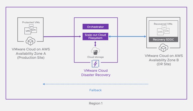
In a previous post, I covered how VMware Cloud Disaster Recovery can help customer address the process of recovering workloads from a disaster.
Ransomware attacks against corporate data centers and cloud infrastructure are growing in complexity and sophistication, and are challenging the readiness of data protection teams to recover from an attack.
In this post, I will cover the Ransomware Recovery add-ons that have been recently added to VCDR and how it can help enterprise to address recovery from Ransomware.
What is a Ransomware attack?
Once ransomware enters a system, it begins encrypting individual files or complete file systems. It blocks user access until requests for payments, which are often displayed in warning messages, are fulfilled. Unfortunately, even if the organization pays the ransom, there is no guarantee that the perpetrators will provide the cryptographic keys needed to decrypt the files.
Ransomware attacks are very unpredictable. They do happen. When you think about Ransomware attacks, they come in different form and sizes, and it makes it very difficult to plan the recovery effort without the proper tooling in place.
The Cert common attack paths of a human-operated ransomware incident based on examples CERT NZ has seen is represented in the below image.
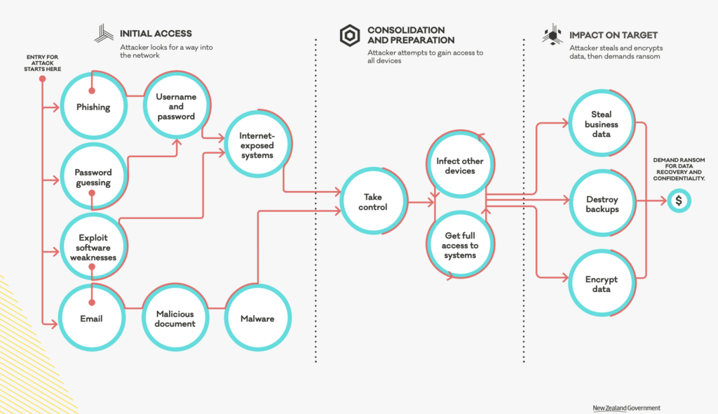
Ransomware attacks use different techniques and technics to infect your system and establish persistently, move laterally, and encrypt your data. It’s hard to know how you are going be attacked. It’s also difficult to anticipate the scale of the attack. It may be a few VMs or a large chunk of the VM estate that gets attacked.
Another factor which is difficult to anticipate is the dwell time: how long the bad code will stay on your system before you notice it is there. In smaller IT organisation that don’t have a large security team or budget, it can be up to 43 days on average. On larger enterprise, as budget increases, and the security team presence increases, tooling gets better, and the average dwell time is around 14 to 17 days.
Why should I consider VMware Ransomware Recovery?
According to NIST, a robust ransomware protection plan must have both preventative as well as recovery measures.
Preventative measures help prevent ransomware from getting into the environment in the first place, and if it does, to contain and eradicate it before it causes widespread damage. At VMware, we have products that address this such as Carbon Black and NSX with features like NSX Network Detection and Response NDR, NSX Distributed IDS/IPS, per application micro-segmentation or multi-hop Network Traffic Analysis.

But recovery measures are always required because preventative measures cannot make an organization fully immune to ransomware, and that is what we’re addressing here – the last two stages of ransomware recovery that serves as that critical last line of defense in case all preventative measures fail. An important point to note here is that the security team is primarily responsible for the preventative measures, but the core responsibility for ransomware recovery falls on the infrastructure team.
The threat of ransomware to the global business environment has reached epidemic proportions. According to a recent Bitdefender report, ransomware attacks grew more than 700% year-on-year in 2020, and an Atlas VPN study (via AiThority) found that ransomware attacks now command an 81% share of all financially motivated cyberattacks.
It’s getting vital for enterprise to have a solid Ransomware recovery in place as it’s the last line of defense.
What Makes VMware Ransomware Recovery Different?
VMware Cloud Disaster Recovery is already a great Ransomware Recovery platform with many capabilities as best practice to implement RWR.
True Air-Gapped, immutable recovery point filesystem
No access points, no NFS Mount, no FS to browse. Data goes into our native application and there are stored in immutable format because we never do an overwrite. In addition we use a log structured file system that is totally air gapped. No one can browse, no one can delete the data.
Instant Power on
It gives us something that no cloud backup vendor can do: any backup, at any point in time can be turn on instantly without any data rehydration and zero copy. Any snapshots can be turned on and registered in the recovery SDDC running in the Cloud in a matter of seconds. Which gives a great capability to iterate. We give also automation to power off, bring up and try the next one.
Deep snapshot history
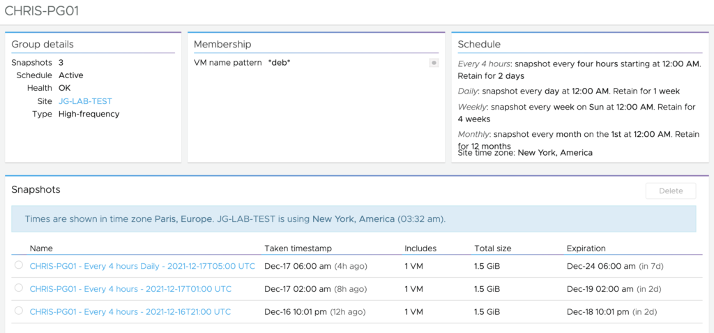
With VMware Cloud Disaster Recovery, it is possible to keep a wide variety and retention of recovery points to draw from. We have deep snapshot history from hours, days, even up to months and can recover all of these snap without any RTO penalty. This is clearly important when you want to make sure you can recover your data before the bad code lands on your system.
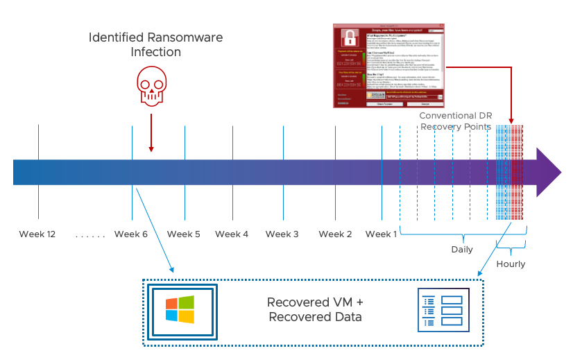
This is critical if simply rolling back in time to a recent clean recovery point is not possible. It is possible to bring more recent, still accessible VM instances into inventory, set them aside, and then copy their data into a clean VM recovery instance from an earlier point in time – potentially even before any attack was present.
What new capabilities were added to address Ransomware Recovery?
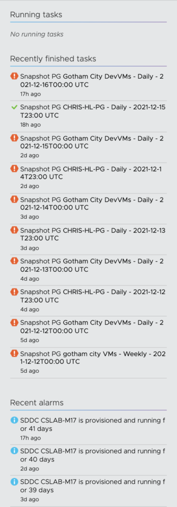
One of the first customer challenge in Ransomware Recovery is identifying the right recovery point candidates. That can be a daunting task as there are going to be a lot of snapshots to look at. And it’s very difficult to know when your system was infected or encrypted.
The next step after deciding which restore point to pick is validating the restore point. How do I know if this restore point is good? Maybe it’s not encrypted, but how do I know the bad actor is still there? If I’ve created a restore point and the malicious code is still there. How do I know it’s a good one? Maybe it’s not encrypted but what if the bad actors are still on the machine or if I stood up a restore point that still have the malicious code.
In addition, to avoid reinfection, VMs need to be evaluated in an isolated environment, which can be complex to setup and maintain.
In order to address those key challenges of the Ransomware recovery, we have added very powerful capabilities to VCDR that are truly differentiated from any other vendors!
A Dedicated Ransomware Recovery Workflow

When you are experiencing a ransomware and going into the process of recovering from it, above all, there is a task which can be very time consuming which is the creation of a workflow or a runbook at the moment you realize that you have been attacked. What we are offering to customer there, is the ability to be guided through the recovery process by providing a dedicated workflow. This is an important feature in a time saving perspective especially during that stressful time.
This workflow provides the ability to run a specific dedicated Recovery Plan for ransomware recovery that includes multiple tasks. When executing these tasks, the Virtual Machines are going to move into 3 stages: In validation, Staged, Restored.
During the first step, you are going to move the VM snapshots from “in backup” stage to the in validation stage. It means that you will start them into the Recovery SDDC environment to validate them.
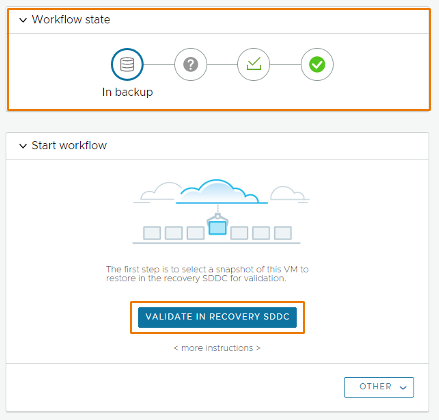
Just after clicking the Validation button, VCDR will use the Live Mount feature to instantly power on the selected VM snapshots in a quarantine state (snapshots will be isolated from each others). Live Mount means the ability for hosts in VMware Cloud on AWS to boot VMs directly from snapshots stored securely in the Scale-out Cloud File System which is backed by Cloud Native storage.
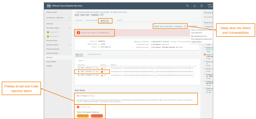
After, if you opt-in for the integrated security scanning, it will automatically install a security sensor (Carbon Black agent) on Windows VMs (manually on Linux VMs) and immediately begin performing a behavior analysis on the running machines. Behavioral analysis will continue running for a recommend minimum of 8 hours.

During that stage, you will be able to monitor the security events and alerts generated by the scan, change the isolation level, restore files from other snapshots and review the snapshot timeline to analyze change rate and entropy level (see below for the explanation). This will help you decide if the snapshot can be approved for production or not.
If you consider the snapshot still present a risk to host a malicious code or that there are encrypted content, you can badge the snapshot to quickly identify the infected snapshots.
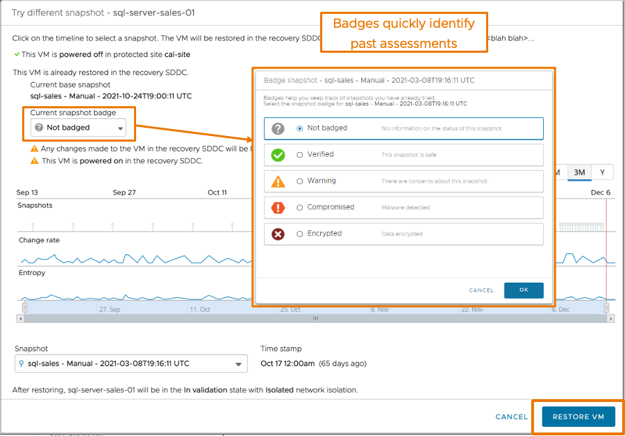
Snapshot badges include:
- Not badged: no information on the security status
- Verified: Snapshot is safe
- Warning: some of the data of the snapshot might be compromised
- Compromised: snapshot has some vulnerabilities and malware infection
- Encrypted: data in the snapshot has been encrypted
At that stage you can consider the snapshot is compromised and restart a validation process again from a different snapshot.
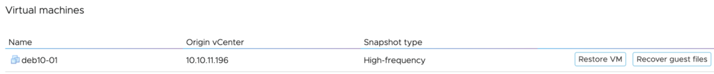
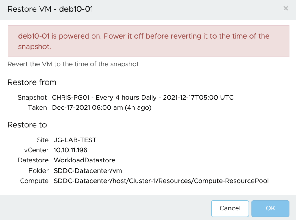
If you decide the VM snapshot is not compromised, you can move it to the Staged stage. The system will then power off the validated VM and take a snapshot of it to prepare it to for recovery to the protected site. For Windows VM, the security sensor will be automatically removed. For Linux VM, you will have to uninstall it prior to the staging phase.

A Guided Restore Point Selection
This means whenever you have that sea of snapshot to select from where to begin, we offer you guidance on which snapshots potentially are encrypted. So that you don’t loose time to select those that are encrypted or compromised snapshots.
This will be possible over the snapshot timeline that appears when you first start VMs in validation stage and select from the Timeline tab and when you try a different snapshot during the validation process.
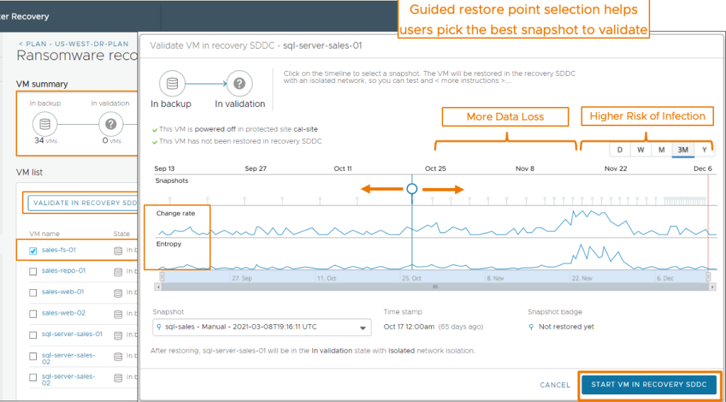
Let say there have been an encryption through a malware, the guided workflow will help you pull the VMs into a guided restore point selection where you will be able to check two different metrics: Change rate and Entropy Level.
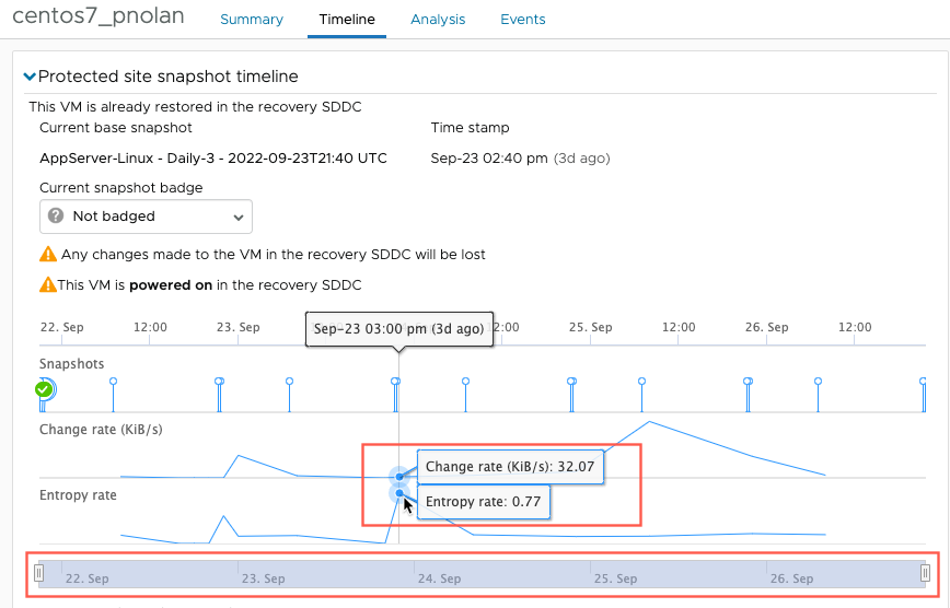
Change rate
The number of bytes changed that we divide by the time difference between the current snapshot and the previous snapshot.
Entropy level
The entropy level is a metric measuring the level of consistency between files in the disks. This is based on the calculation opf the Entropy rate which corresponds to the following formula: 1/compression ration. The Entropy rate is a number between 0 and 1, and the closer it is to 1, the higher the likelihood the snapshot has been encrypted. Sudden jumps in entropy level is a clear indication of a possible encryption.
Both metrics are calculated and displayed in the Timeline tab when you select a VM for testing.
When VCDR detects higher change and entropy rate, it can indicate that a ransomware attack encrypting the data is ongoing or has happened. It is then recommended to pick the snapshot before the onset malware activity as it may content unencrypted data.
Behavioral Analysis of Powered-on VMs

Inspection of powered-on workloads in isolation with embedded Next-Gen AV (NGAV) and Behavior Analysis helps detect abnormal activities.
This is another great differentiator. Anytime you look at competitive offering and see how scanning of snapshots is realized. Hackers know exactly how scanning for a file signature can be easily avoided. They do avoid it. Whenever bad guys go after systems they use file less method: they work in memory, they elevate their privileges.
When you start a VM in ransomware recovery on the recovery SDDC, a next generation antivirus that is using ML/AI scans for known vulnerabilities and for malware signatures, and a deep behavior analysis begins of all running software and processes on the VM guest OS, looking for suspicious behavior.
The Vulnerability tab shows a list of all found vulnerabilities with their CVE number and a link to the vulnerability article in the National Institute of Standards and Technology (NIST) database.
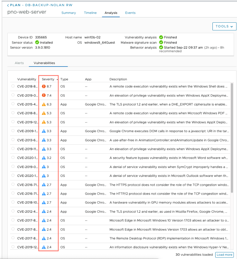
Once the vulnerability scanning completes, you can remediate them by patching the VM directly from the IRE and execute a new scan once the remediation is completed.
The behavioral analysis is conducted in parallel and it analyzes VMs and their guest files for abnormal behaviors like processes that make outbound connections or malicious interference with the Windows registry.
The results of the malware scan and behavior analysis displayed in the Alerts tab and ranked according to severity, with a higher score being worse than a lower score.
If you opt-in for the integrated analysis that is powered by Carbon Black, you can also view VMS in the Carbon Black Cloud console for further analysis.
An Isolated Recovery Environment (IRE) & push-button VM Isolation levels
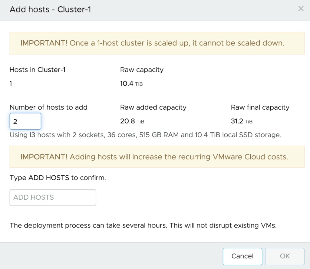
One other important differentiator is that you can provision an On-Demand Isolated Recovery Environment (IRE) – a quarantined or sandboxed environment – on VMware Cloud on AWS for testing and validating the recovery points.
VMware Cloud on AWS SDDC works very well as an isolated environment and it offers a great on-demand option to help save money. You have the choice to consume it on-demand or as a Pilot Light to have two nodes minimum waiting for the DR event to happen. The Pilot Light option is a better option when you are looking for the lowest RTO.
With VMware Cloud on AWS is a “safe” place to spin up VMs to prevent your production environment from seeing reinfection, it’s a true sandbox environment.
Having this dedicated, secure environment for validation and testing is critical for preventing reinfection of the production workloads, and we’re able to bring this up on-demand, as a fully VMware-managed environment.
Additionally, we have push-button VM network isolation levels that allows you to easily assign network isolation policies to VMs to prevent lateral movement of the malware within the Isolated Recovery Environment. This is possible through the use of NSX Advanced Firewall within VMware Cloud on AWS SDDC. We offer user a push button method with 7 preconfigured isolation levels to take all the work out of the administrator.

Please note that VMs always start in isolation mode which means those VMs can only connect over the internet to the NGAV Tools (integrated security and vulnerability servers on Carbon Black Cloud) and to basic network services like DNS and NTP, all other north/south or east/west network traffic is limited through NSX Firewall rules. Changing the isolation is always possible by changing the network isolation rule.
Conclusion
66% of organizations woke up to a ransomware attack in the last year. In 65% of those organizations, attackers got past the security defenses and actually encrypted data for ransom. Ransomware attacks against corporate data centers and cloud infrastructure are growing in complexity and sophistication, and are challenging the readiness of data protection teams to recover from an attack.
In order to solve these key challenges, VMware offers a solution that addresses both the on-demand disaster recovery use case, as well as the next-gen ransomware recovery use case.
When it comes to the ransomware recovery use case, we have very powerful capabilities that are truly differentiated from anything that is out there today.
We offer a lot of capabilities to address the challenge:
- Deep snapshot history from hours, days and months
- Recovery from any snapshots without any RTO penalty
- Air-gaped and Immutable by design system
- Instant Power-On
- File/folder Restore
- Isolated Recovery Environment (IRE)
- Restore point validation with Embedded Behavioral Analysis
- Push-button VM Isolation levels
A proper ransomware recovery solution requires security, backup, networking, compute and storage to come together. VMware has uniquely taken all of these elements, as well as the best practices when it comes to recovering from ransomware attacks, and put them together into a cohesive and integrated solution that helps customers minimize data loss and accelerate recovery.