I have seen a lot of customers having overlapping IP subnets among their applications and who wanted to avoid renumbering their network segments when they migrate them to the cloud.
In the recent 1.18 release of VMware Cloud on AWS, we have added the ability for customers to create additional T1 Compute Gateways . Additional T1s can be used for a number of use cases including environment segmentation, multi-tenancy and overlapping IP addresses.
In this blog post, I am going to cover the specific design case where a native VPC needs to connect with a segment in an SDDC that has an overlapping subnet with another segment. The SDDC itself is using a Route Based VPN to connect to a native AWS Transit Gateway where the native VPC is peered.
Lab topology
First of all, I have deployed my SDDC in the Northern Virginia region. Straightaway I have attached it to a native Transit GW over a Route Based VPN (I wanted to leverage BGP for dynamic routes exchange).
I then have attached the native VPC to the native TGW through a normal peering connectivity.

N.B.: I took the assumption that I would need a route aggregation for route advertisement as it’s a requirement for the Multiple Compute Gateway case. A key point in that case is that it’s not using Transit Connect, Direct Connect, or Connected VPC, so I don’t need a route aggregation.
Additionally in this SDDC, I have created two Compute segments that are using overlapping IPs (172.20.2.0/24).

On the AWS native side, there is 1 EC2 instances (172.20.5.153) in a native VPC (172.20.5.0/24) and on the SDDC I have deployed a Debian10 Virtual Machine named Deb10-app001 running with IP 172.20.2.100.

Inside the SDDC, I have attached the VM to the Overlapped segment as you can see it here:

Implementing the lab topology
Creating the New CGW
There are three different types of Tier-1 Compute Gateways that can be added with M16: Routed, Isolated and NATed. In this example, I have chosen the NATed type. This CGW type allows for communication between segments but avoid that any segments to be learned by the Tier-0 router. This also avoid having their CIDRs show up in the routing table.
To create the new NATed CGW, I went to the Tier1-Gateways menu and click on the “ADD TIER-1 GATEWAY” button. In addition, I have made sure I pick NATed as the type.

I know have a new Tier-1 Compute Gateway.
Creating a new overlapping segment
Equally, I have created the overlapped segment and have attached it to the new NATed CGW Compute Gateways. I have picked the ‘T1 NATed’ CGW in the list.

Creating a DNAT Rule
In order to ensure connectivity to the SDDC’s overlay segments configured behind them we need to configure a NAT Rule on the NATed CGWs.
So the last step was to create a DNAT Rule and attach it to the T1 NATed Compute Gateway.
For that I went to the NAT Menu on the left and have selected the Tier-1 Gateway tab and pick the T1 NATed GW.

I have just clicked on the ADD NAT RULE button. I have enter the NATed subnet in the destination IP/Port field (192.168.3.0/24 in this example) and the overlapped subnet as the destination.

This means that any IP I want to reach inside 172.20.2.0/24 like 172.20.2.100 will be accessible over the Nated IP 192.168.3.100.
Next step is to click on the Set to select the right T1 Gateway to apply the rule to and picked the T1 Nated Gateway:

After a couple of seconds, I have confirmed the rule gets activated by checking the rule status:

Adding the right Compute Gateway Firewall rule
Next thing I did to finish the setup is to add the right firewall rule on the new T1 Gateway. Remember each T1 has its own FW rules.
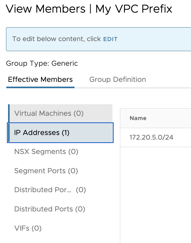
In this case, I have created a new group called ‘My VPC Prefix’.
I have, however, created another group with the CIDRs I used to map the ‘Overlapping Segment’:

I then have created the Compute Gateway Firewall rule called ‘ToDNAT‘ with the group “My VPC Prefix” as the source and the IP address of my NATed segment as the destination with ‘SSH’ and ‘ICMP ALL’:

Testing the lab topology
Checking the routing
First let’s check the routing inside the VPC. We need to add a static route back to the SDDC NATed segment CIDR: 192.168.3.0/24. Thanks to that, the VPC will send all traffic destinated to the NATed CIDR over the TGW peering.

As there is a Route Based VPN between the SDDC and the TGW, the TGW route table is automatically advertising the SDDC NATed CIDR (192.168.3.0/24) that I will use to connect to the overlapped segment (172.20.2.0/24).

Pinging from the VPC
To test my lab connectivity, I have connected to the instance created in the AWS native VPC (172.20.5.0/24) and try to ping the 192.168.3.100 Ip address and it worked!

In this blog post I have demonstrated how to connect to an overlapped SDDC segment by creating an additional NATed CGW. In this example, I have connected from a VPC attach to a TGW connected to the SDDC over a VPN .
I hope you enjoyed it!
In my next blog post, I will show you how to do the same over a Transit Connect, stay tune!
One thought on “How to leverage NATed T1 Gateway for overlapping networks over a Route Based VPN to a TGW”