In the previous posts of this series on Configuring a VPN connection from WatchGuard TM Firebox to VMC, I have showed you how to setup the Firebox and how to establish a VPN with a native VPC.
In this last post, I will attach the SDDC to the WatchGuard Firebox instance with a IPSEC route-based VPN leveraging BGP to allow for dynamic routes exchange.
With this configuration, any compute and management segments created inside the SDDC will be the advertised into the BGP session established with the Firebox in the transit VPC.
Firebox to SDDC IPSec VPN configuration
Phase 1 – VPN’s VPC configuration
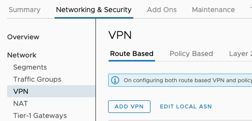
First of all I need to collect the public IP address of my SDDC. This is possible by logging to the VMC Console and going to the Networking and Security tab, and Selecting the Overview window:
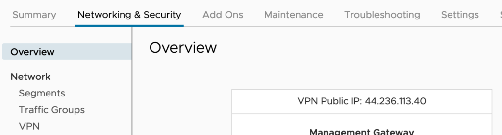
N.B.: You can also request additional public IP addresses to assign to workload VMs to allow access to these VMs from the internet. VMware Cloud on AWS provisions the IP address from AWS.
Next I’ll collect the BGP local ASN number of the SDDC. Just like IP addresses, ASNs (Autonomous System Numbers) have to be unique on the Internet and the SDDC utilises two numbers: one for the route-based VPN and one for Direct Connect.
To do that I Click on Edit Local ASN option in the VPN window:
Clicking EDIT LOCAL ASN displays the Local ASN of the SDDC as shown here:
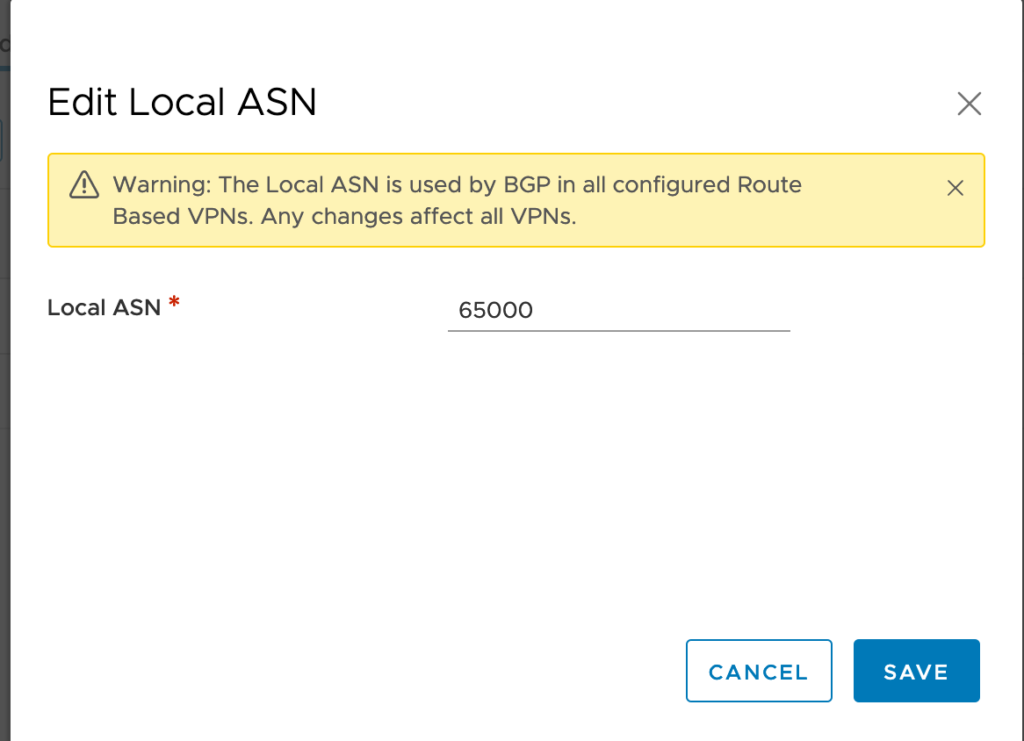
The local ASN of any brand new SDDC is by default at 65000. You can change it to a value in the range 64521 to 65535 (or 4200000000 to 4294967294).
N.B.: Keep in mind that the remote BGP ASN number need to be different.
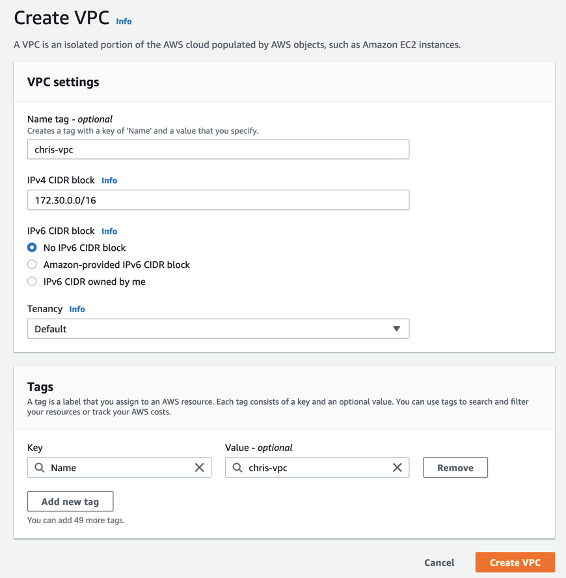
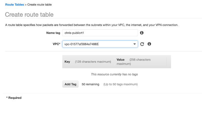
Now it’s time to create a new Customer Gateway and map it to the SDDC settings.
Create a New Customer Gateway
For that I need to go back to the AWS console and Go to the VPC Dashboard and Select Customer Gateways under VIRTUAL PRIVATE NETWORK Menu on the left.
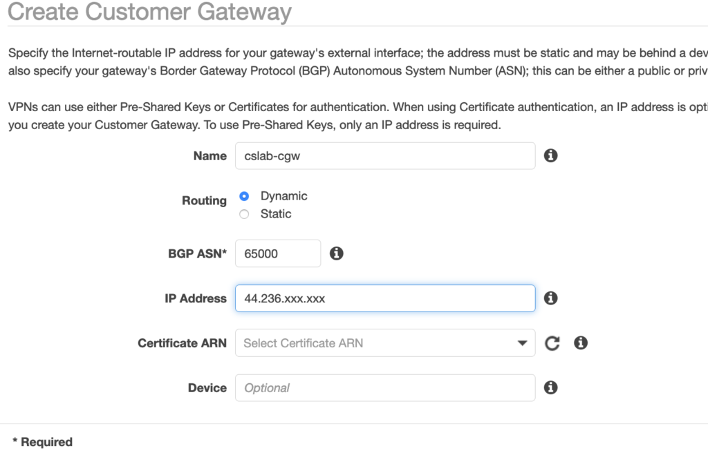
I Click Create Customer Gateway and choose Dynamic as a routing option, and add the public Elastic-IP address of the SDDC public IP.
I also need to specify the BGP ASN to the SDDC value (65000 by default). Note that it has to be different from the BGP ASN of the Firebox in the transit VPC.
Phase 2 – FireBox’s VPN Configuration
Now I have to setup the VPN configuration on the Firebox itself. For this, I connect back to the Fireware Web UI:
- Open a web browser and go to the public IP address for your instance of Firebox Cloud at: https://<eth0_public_IP>:8080
- Log in with the admin user account. Make sure to specify the passphrase you set in the Firebox Cloud Setup Wizard.
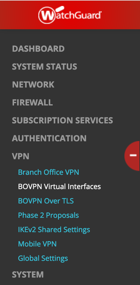
Select VPN, BOVPN Virtual Interfaces on the left and click the lock to open the settings window.
Enter a name for the interface (eg. BoSddc) and switch the Remote Endpoint Type to Cloud VPN or Third-Party Gateway.
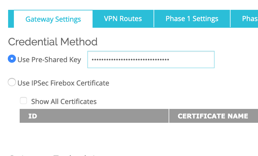
In the Gateway Settings-> Credential Method, Enter a Use Pre-Shared Key (note the key as you will have to use it in the SDDC setup):
In the Gateway Settings–>Gateway Endpoint–>Click ADD.
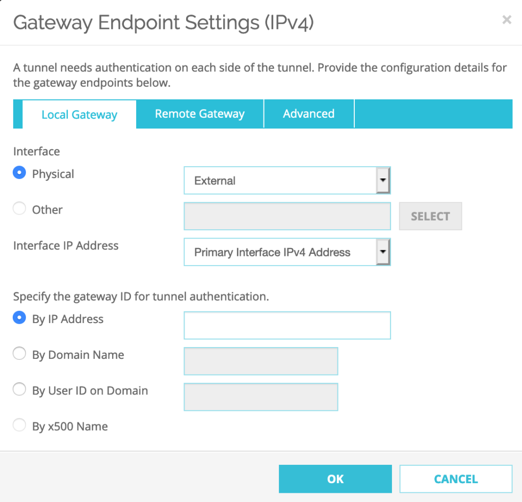
Select Local Gateway–>Interface: Select Physical: External
Specify the gateway ID for tunnel authentication: Select By IP address: 34.210.196.xxx (this is the public Elastic-IP of the Watchguard Firebox)
Select Remote Gateway–>Specify the remote gateway IP address for a tunnel: a the Static IP Address has to be set to the Public IP address of the SDDC:
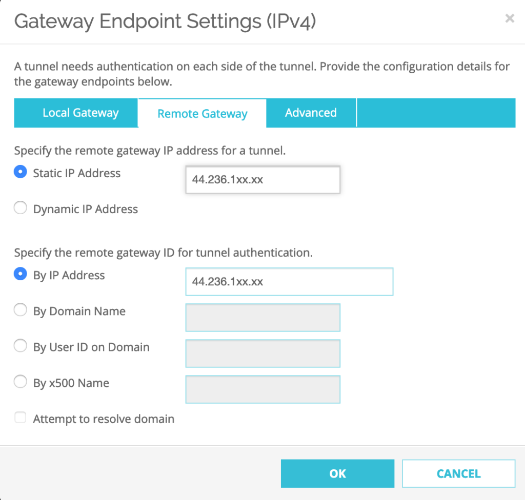
Next Step, Select Advanced tab and Click OK
Configure Phase 1 of IPSEC Proposal
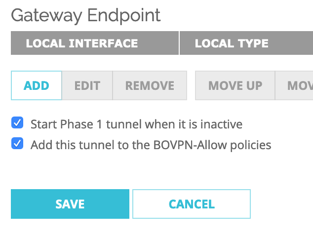
Check ‘Start Phase1 tunnel when it is inactive‘ and Keep the ‘Add this tunnel to the BOVPN-Allow policies‘ checked.
The Phase 1 Settings should be as follow:
1. Version: IKEv1
2. Mode: Main
3. Uncheck NAT Traversal
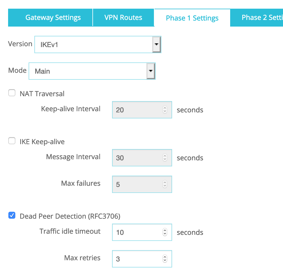
N.B.: NAT Traversal is enabled by default but if your WatchGuard device is not behind a NAT/PAT device, please deselect NAT Traversal.
Dead Peer Detection:
a. Traffic idle timeout: 10
b. Max retries: 3
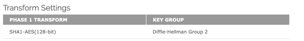
Transform Settings–>Click ADD:
1. Authentication: SHA1
2. Encryption: AES(128-bit)
3. SA Life: 8 hours
4. Key Group: Diffie-Hellman Group 2
Click OK.
Remove any pre-existing Phase 1 Transform Settings eg. SHA1-3DES.
Configure Phase 2 of IPSEC Proposal
Go to VPN–>Phase2 Proposals–>Click ADD
Name: AWS-ESP-AES128-SHA1
Description: AWS Phase 2 Proposal
Type: ESP
Authentication: SHA1
Encryption: AES(128-bit)
Force Key Expiration: Select ‘Time’ -> 1 hours
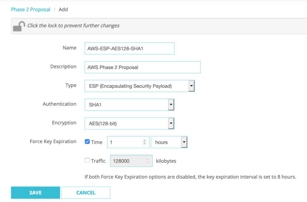
Click SAVE.
Go to VPN–>BOVPN Virtual Interfaces–>Select BoSddc–>Click EDIT
Phase 2 Settings–>Perfect Forward Secrecy:
Check ‘Enable Perfect Forward Secrecy’: Diffie-Hellman Group 2
IPSec Proposals–>Click on existing proposal–>Click REMOVE
Select ‘AWS-ESP-AES128-SHA1’ from the drop-down menu–>Click ADD
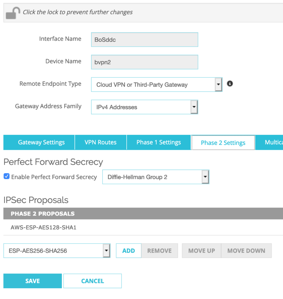
Click SAVE.
Configure BGP dynamic routing.
Go to VPN–>BOVPN Virtual Interfaces–>Select BoSddc–>Click EDIT
For the VPN Routes settings, I keep ‘Assign virtual interface IP addresses‘ option checked for the Interface option.
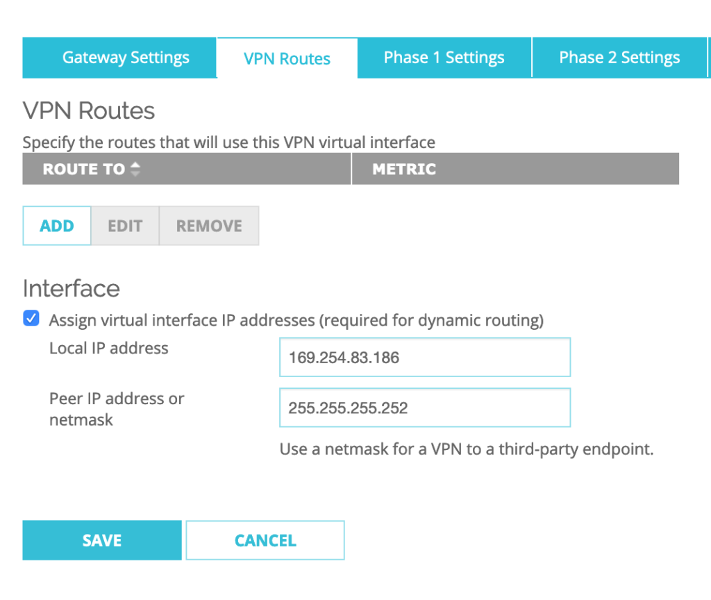
Then I setup the Local IP address to: 169.254.85.186 and Peer IP address or netmask to: 255.255.255.252
then Click SAVE.
Go to Network–>Dynamic Routing and Check ‘Enable Dynamic Routing’.
Click on ‘BGP’: Check ‘Enable’
I have to Add the below BGP dynamic routing configuration commands in the box:
router bgp 65001 — N.B.: Use this command only once at the beginning of the BGP config as this the local ASN number that the Firebox will use for any VPNs.
NOw it’s time to add the configuration for the second BGP neighbor that we need to configure for the SDDC:
neighbor 169.254.85.185 remote-as 65000
neighbor 169.254.85.185 activate
neighbor 169.254.85.185 timers 10 30
Click SAVE.
Phase 3 – VMC on AWS SDDC’s VPN Configuration
VMC on AWS allows to create up to 4 IPSEC route-based VPN tunnels to be established between Firebox/VPC and your SDDC. To create the VPN on the SDDC side, you first have to Connect to the SDDC console.
Then you need to Go to the Networking & Security tab.
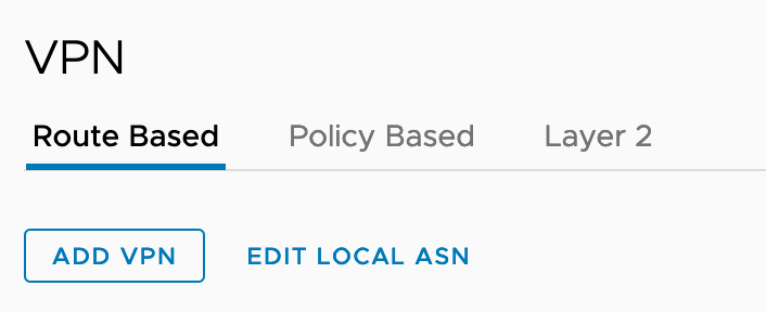
Select Network -> VPN and Click on the Route Based tab.
Click ADD VPN.
Next, you have to enter the following configuration settings:
- First give a name to the IPSec VPN (eg. TOFirebox).
Select Local Public IP1 of the SDDC: this is the public IP address of the SDDC. As the Remote Public IP, Select the Elastic IP that was assigned to the public interface of the Watchguard Firebox FW. The Remote private IP is automatically entered.
For the BGP Local IP/Prefix Length, choose the following: 169.254.85.185/30.
The BGP Remote IP is the Local IP configured previously in the VPN Routes of the BOVPN Virtual interfaces: 169.254.85.186.
BGP Neighbor ASN has to be he remote ASN of the WatchGuard Firebox: 65001.
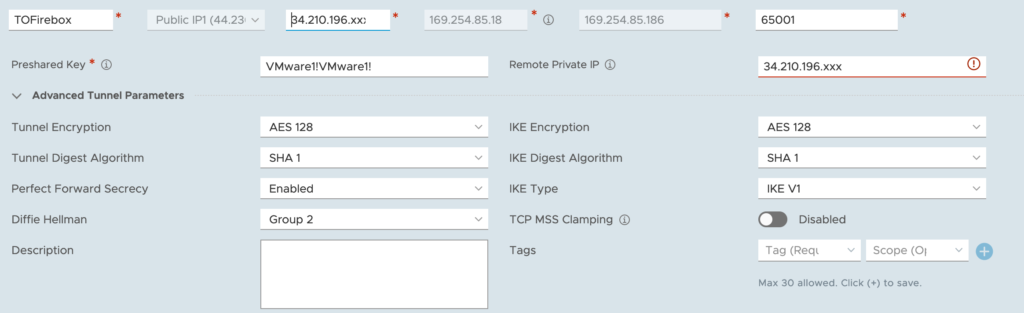
- Tunnel Encryption: AES128
- Digest Algorithm: SHA-1
- PFS: Enabled
- Diffie-Hellman: Group 2
- IKE Encryption: AES128
- IKE Digest: SHA-1
- IKE Type: V1
After a few seconds, we can see that the VPN is up!